

Power factor correction
The Aunilec capacitor banks allow the increase of the energetic performance by improving the cosphi of an electrical installation polluted by loads, which leads to significant energy savings. Moreover, the increase of the power factor determines a reduction of the losses with very important advantages for the system. Industrial installations particularly require the use of automatic capacitor banks to compensate for the reactive energy produced by the motors and connected loads. The main advantages of capacitor banks are: reduction of the electricity bill, increase of the system power, improvement of the voltage and reduction of losses. There are several types of capacitor banks, please contact us to get a solution adapted to your needs.
-

Serie B25
Power factor correction in presence of harmonics
In recent years, Power Factor Correction has evolved greatly due to the presence of generated harmonics by the loads.
These loads produce harmonic currents and voltage which distorts the network waveforms. The main sources of harmonics are generated by AC/DC static converters and UPS systems. For these reasons it is essential that any installation of Power Factor Correction equipment must be carefully evaluated.
The possible presence of harmonic currents in the network could create conditions of parallel resonance between the inductance of the network and the capacitors, generating overcurrents and overvoltages, which would cause premature failure of the power factor correction capacitors. The ideal power factor correction solution for any system must be determined by examination of the system parameters and harmonic spectrum.
-


Serie B35
Power factor correction in presence of harmonics
In recent years, Power Factor Correction has evolved greatly due to the presence of generated harmonics by the loads.
These loads produce harmonic currents and voltage which distorts the network waveforms. The main sources of harmonics are generated by AC/DC static converters and UPS systems. For these reasons it is essential that any installation of Power Factor Correction equipment must be carefully evaluated.
The possible presence of harmonic currents in the network could create conditions of parallel resonance between the inductance of the network and the capacitors, generating overcurrents and overvoltages, which would cause premature failure of the power factor correction capacitors. The ideal power factor correction solution for any system must be determined by examination of the system parameters and harmonic spectrum.
-


Serie B50
Power factor correction in presence of harmonics
In recent years, Power Factor Correction has evolved greatly due to the presence of generated harmonics by the loads.
These loads produce harmonic currents and voltage which distorts the network waveforms. The main sources of harmonics are generated by AC/DC static converters and UPS systems. For these reasons it is essential that any installation of Power Factor Correction equipment must be carefully evaluated.
The possible presence of harmonic currents in the network could create conditions of parallel resonance between the inductance of the network and the capacitors, generating overcurrents and overvoltages, which would cause premature failure of the power factor correction capacitors. The ideal power factor correction solution for any system must be determined by examination of the system parameters and harmonic spectrum.
-

Serie AR180
Power factor correction in presence of harmonics
In recent years, Power Factor Correction has evolved greatly due to the presence of generated harmonics by the loads.
These loads produce harmonic currents and voltage which distorts the network waveforms. The main sources of harmonics are generated by AC/DC static converters and UPS systems. For these reasons it is essential that any installation of Power Factor Correction equipment must be carefully evaluated.
The possible presence of harmonic currents in the network could create conditions of parallel resonance between the inductance of the network and the capacitors, generating overcurrents and overvoltages, which would cause premature failure of the power factor correction capacitors. The ideal power factor correction solution for any system must be determined by examination of the system parameters and harmonic spectrum.
-


Serie AR140
Power factor correction in presence of harmonics
In recent years, Power Factor Correction has evolved greatly due to the presence of generated harmonics by the loads.
These loads produce harmonic currents and voltage which distorts the network waveforms. The main sources of harmonics are generated by AC/DC static converters and UPS systems. For these reasons it is essential that any installation of Power Factor Correction equipment must be carefully evaluated.
The possible presence of harmonic currents in the network could create conditions of parallel resonance between the inductance of the network and the capacitors, generating overcurrents and overvoltages, which would cause premature failure of the power factor correction capacitors. The ideal power factor correction solution for any system must be determined by examination of the system parameters and harmonic spectrum.
-
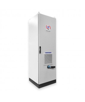
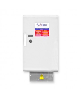
Serie QSRB25
Capacitor bank without regulation known as fixed compensation
Used when reactive power to compensate is constant and when the load is working 24h / 24h.
Used when reactive power is to compensate for low power. Also standardized by the coefficient QC (Compensation to install in KVAR) / SN (Transformer power in KVA) is generally <15%. This threshold of 15% is indicative and we recommend it to avoid to overcompensate the charge power vacuum.
Used to directly compensate the asynchronous motor, load losses of the line head transformer.
-

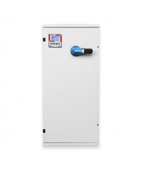
Serie QSRB35
Capacitor bank without regulation known as fixed compensation
Used when reactive power to compensate is constant and when the load is working 24h / 24h.
Used when reactive power is to compensate for low power. Also standardized by the coefficient QC (Compensation to install in KVAR) / SN (Transformer power in KVA) is generally <15%. This threshold of 15% is indicative and we recommend it to avoid to overcompensate the charge power vacuum.
Used to directly compensate the asynchronous motor, load losses of the line head transformer.
-

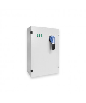
Serie AST
Static power factor correction capacitor
The reactive power regulator has a switching time of the banks extremely quicker than the standard regulator. The device for switching the capacitors banks is electronic, controlled by thyristors, with the capability of switching the capacitors at zero crossing. Maximum speed in switching the capacitors banks (the total power is switched in less than one second). No current peak on the capacitors at the time of switching of the banks. No voltage peak on the capacitors at the time of switching off the banks. Elimination of problems related to contactor contact wear.
-
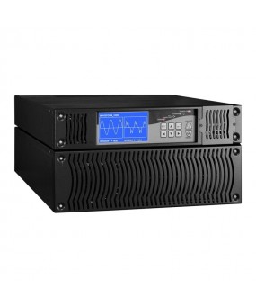
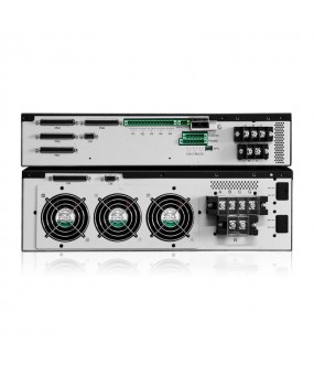
Serie FAFW34030
Harmonic current generator
The Aunilec APF behaves like an harmonics current generator. It will measure the harmonic generated from the non-linear loads and cancel these harmonics with an opposite phase at the same amplitude.
Power factor correction
The Aunilec APF not only compensate harmonic current but also the reactive power. It is able to correct for either a leading or lagging power factor.
LCD display
The user friendly LCD display offers access to all parameters, waveforms, harmonic spectrum system power quality, settings, status and alarms, events log and language selection.
-
Serie FAFW
Active filtering and power quality
FAFW is the new generation of active harmonic filters. It reliably mitigates harmonics and compensates voltage dips as well as reactive power. The FAFW analizes network disturbances and provides an opposing compensation current. In doing so, FAFW actively adapts to fluctuations and responds in less than half a millisecond. Its compact dimensions, simple installation, and digital intelligence allow for a quick and straight forward integration in the most diverse applications.
These products allows to reinject a current corresponding to the total harmonic component (the first order). By this way, the network is traversed by a current equal to the single fundamental component.