
Home
Subcategories

-
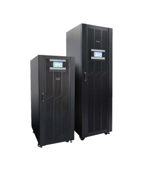
IRIS+T 10/15/20 kVA
The IRIS+T is currently the most compact double conversion UPS system with 3-phase input and 1-phase output for use in the smallest space. It can be extended extremely fl exibly in terms of autonomy time by means of external battery packs. In addition, the input can also be confi gured as 1-phase in addition to 3-phase.
-
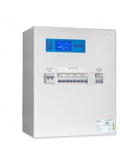
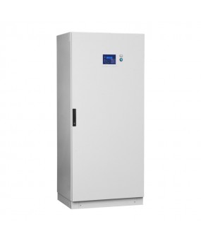
AESA tower
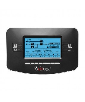
LCD Display
The LCD display controlled by microprocessor allows the visualization of current and voltage parameters.
BC panic option
Getting voluntary sleep mode mood lighting (separate box/cabinet). Combined with a permanent central source, it switches the mood lighting (anti-panic) permanent in non-permanent mode. Recovery in continuous operation can be done at any time manually or automatically on disappear sector.
Remote control panel option
The alarm report box includes 4 free entries relay contact associated with LEDs on the front.
-
- New
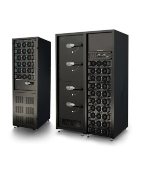
HELIOS-MP2
Aunilec’s HELIOS-MP2 modular range has been efficiently protecting the supply of critical applications around the world for almost a decade. With thousands of power modules deployed across the globe, it is recognised as a high performing and ultra-reliable system. HELIOS-MP2 is the evolution of our modular UPS, which aims to offer higher power density, simpler integration to both existing and new installations and last but not least enhanced operating efficiency and global flexibility to reduce both the upfront investment and the day-to-day operational costs.
-
- New
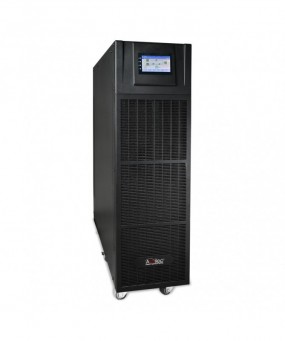
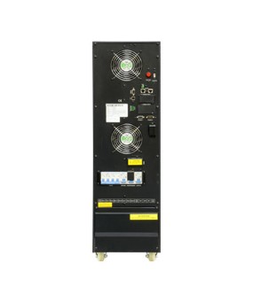
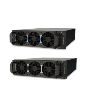
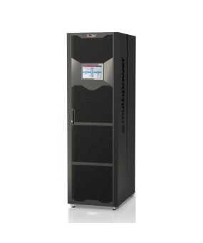
HELIOS-TH
With the HELIOS-TH, Aunilec offers a modern online double conversion ups with 3-phase input & output in 3-level inverter technology, built with powerful 50 kW power modules. Furthermore, battery tests are individually configurable. With an efficiency of over 96 % in normal operation, it is one of the most effective and economical UPS systems on the market and thus ideally suited for saving money.
-
AESB
LCD Display
The LCD display controlled by microprocessor allows the visualization of current and voltage parameters.
BC panic option
Getting voluntary sleep mode mood lighting (separate box/cabinet). Combined with a permanent central source, it switches the mood lighting (anti-panic) permanent in non-permanent mode. Recovery in continuous operation can be done at any time manually or automatically on disappear sector.
Remote control panel option
The alarm report box includes 4 free entries relay contact associated with LEDs on the front.
-
- New
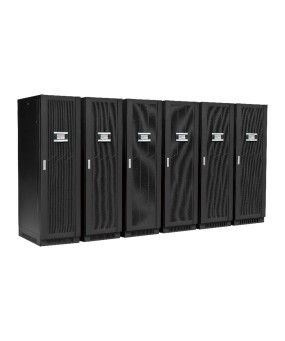
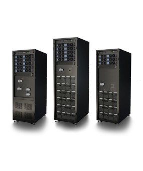
HELIOS-M2X
Aunilec HELIOS-M2X is our next-generation of modular UPS. It’s engineered for unmatched reliability, compactness and sustainability, delivering the best performance available on the market today. It’s the best power solution for Small Data Centers & Critical Applications
-
AESB Eco
LCD Display
The LCD display controlled by microprocessor allows the visualization of current and voltage parameters.
BC panic option
Getting voluntary sleep mode mood lighting (separate box/cabinet). Combined with a permanent central source, it switches the mood lighting (anti-panic) permanent in non-permanent mode. Recovery in continuous operation can be done at any time manually or automatically on disappear sector.
Remote control panel option
The alarm report box includes 4 free entries relay contact associated with LEDs on the front.
-
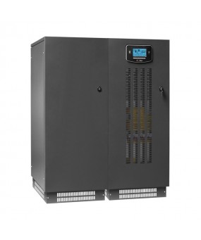
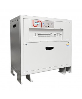
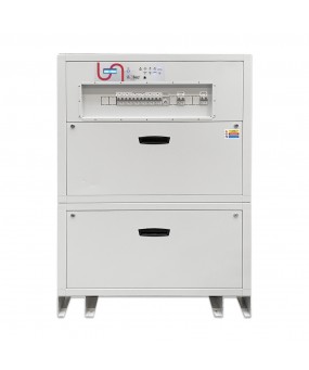
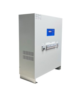
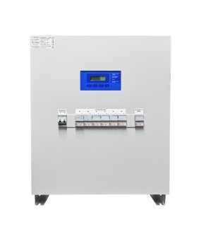
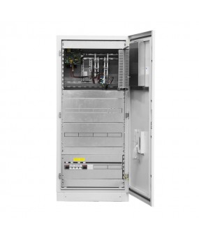
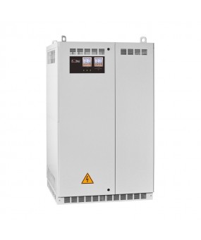
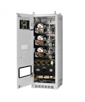
AESATM AESATT
Efficiency
The power sources Aunilec ensure the highest protection and maximum quality of energy for all charges, including for industrial, security systems, electro-medical systems, industrial processes and telecommunications.
The range AESA-TM / TT has an on-line double conversion technology (VFI) making it impossible to interrupt the power supply to the transformer output of the inverter as stipulated by the VFI-SS-111 classification and accordance with IEC EN 62040-3.
AESA-TM / TT range consists of a three phase input and single phase output from 10 to 60 kVA and three phase input and output 10-80 with IGBT rectifier and input power correction factor.
-
RCRFn 24Vcc, 48Vcc, 110Vcc,...
DC power set
These new devices are the result of a research and development by our company, to have maximum reliability and performance in the field of energy supply systems. We have not chosen to implement only the traditional energy conversion systems (isolating transformer with a thyristor), but to liaise flexibility and the advance of a digital logic to a microcontroller.
The electronic controls of the RCRFn rectifiers are reliable and increase the life of batteries.
-
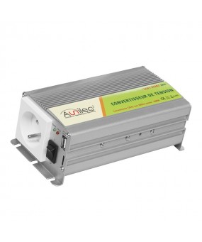
CONV-IN 230V 50Hz
Pseudo-sinusoidal inverter output 230V 50Hz from a 12 or 24V source for leisure applications.
-
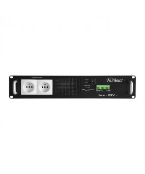
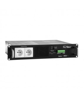
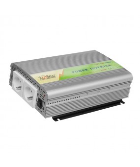
INV 48V 300VA
Inverter INV with DC power supply 48V / 300VA
-
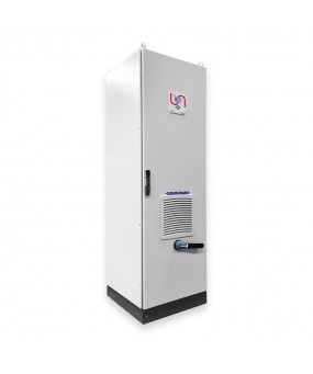
Serie EcoREG
Aunilec proposal
Voltage optimisation is a term given to the systematic controlled reduction in the voltages received by an energy consumer to reduce energy use, power demand and reactive power demand. While some voltage “optimisation” devices have a fixed voltage adjustment, others electronically regulate the voltage automatically. Voltage optimisation systems are typically installed in series with the mains electrical supply to a building, allowing all its electrical equipment to benefit from an optimised supply. Overvoltage leads to sites using more electricity than needed, and as a result incurring higher electricity bills. The overvoltage is not only costly but can also be detrimental to equipment. Excess voltage produces additional noise, heat and vibration, causing stress on internal parts - especially to motors which are vulnerable to overheating and wear out more quickly. Aunilec EcoREG voltage optimisation system ensures that a building only receives and pays for the voltage that it actually needs, and no more.Aunilec EcoREG Voltage Optimisers are available in power rating from 15 to 2600 kVA, single-phase and three-phase versions.
-

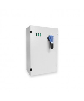
Serie REG-YAC
Highest level of protection
Line conditioners have been designed to provide the highest level of protection to electrical appliances connected to distribution lines disturbed by sudden voltage variations, HF noises and spikes. Statistically, these phenomena represent more than 95% of electric anomalies that could be the cause of breakdowns and poor operation of any kind of appliance connected to distribution lines.
-


Serie B35
Power factor correction in presence of harmonics
In recent years, Power Factor Correction has evolved greatly due to the presence of generated harmonics by the loads.
These loads produce harmonic currents and voltage which distorts the network waveforms. The main sources of harmonics are generated by AC/DC static converters and UPS systems. For these reasons it is essential that any installation of Power Factor Correction equipment must be carefully evaluated.
The possible presence of harmonic currents in the network could create conditions of parallel resonance between the inductance of the network and the capacitors, generating overcurrents and overvoltages, which would cause premature failure of the power factor correction capacitors. The ideal power factor correction solution for any system must be determined by examination of the system parameters and harmonic spectrum.
-


Serie B50
Power factor correction in presence of harmonics
In recent years, Power Factor Correction has evolved greatly due to the presence of generated harmonics by the loads.
These loads produce harmonic currents and voltage which distorts the network waveforms. The main sources of harmonics are generated by AC/DC static converters and UPS systems. For these reasons it is essential that any installation of Power Factor Correction equipment must be carefully evaluated.
The possible presence of harmonic currents in the network could create conditions of parallel resonance between the inductance of the network and the capacitors, generating overcurrents and overvoltages, which would cause premature failure of the power factor correction capacitors. The ideal power factor correction solution for any system must be determined by examination of the system parameters and harmonic spectrum.
-

Serie AR180
Power factor correction in presence of harmonics
In recent years, Power Factor Correction has evolved greatly due to the presence of generated harmonics by the loads.
These loads produce harmonic currents and voltage which distorts the network waveforms. The main sources of harmonics are generated by AC/DC static converters and UPS systems. For these reasons it is essential that any installation of Power Factor Correction equipment must be carefully evaluated.
The possible presence of harmonic currents in the network could create conditions of parallel resonance between the inductance of the network and the capacitors, generating overcurrents and overvoltages, which would cause premature failure of the power factor correction capacitors. The ideal power factor correction solution for any system must be determined by examination of the system parameters and harmonic spectrum.
-

Serie AR140
Power factor correction in presence of harmonics
In recent years, Power Factor Correction has evolved greatly due to the presence of generated harmonics by the loads.
These loads produce harmonic currents and voltage which distorts the network waveforms. The main sources of harmonics are generated by AC/DC static converters and UPS systems. For these reasons it is essential that any installation of Power Factor Correction equipment must be carefully evaluated.
The possible presence of harmonic currents in the network could create conditions of parallel resonance between the inductance of the network and the capacitors, generating overcurrents and overvoltages, which would cause premature failure of the power factor correction capacitors. The ideal power factor correction solution for any system must be determined by examination of the system parameters and harmonic spectrum.
-
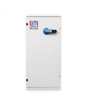
Serie QSRB25
Capacitor bank without regulation known as fixed compensation
Used when reactive power to compensate is constant and when the load is working 24h / 24h.
Used when reactive power is to compensate for low power. Also standardized by the coefficient QC (Compensation to install in KVAR) / SN (Transformer power in KVA) is generally <15%. This threshold of 15% is indicative and we recommend it to avoid to overcompensate the charge power vacuum.
Used to directly compensate the asynchronous motor, load losses of the line head transformer.
-

Serie QSRB35
Capacitor bank without regulation known as fixed compensation
Used when reactive power to compensate is constant and when the load is working 24h / 24h.
Used when reactive power is to compensate for low power. Also standardized by the coefficient QC (Compensation to install in KVAR) / SN (Transformer power in KVA) is generally <15%. This threshold of 15% is indicative and we recommend it to avoid to overcompensate the charge power vacuum.
Used to directly compensate the asynchronous motor, load losses of the line head transformer.
-

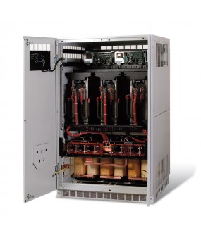
Serie AST
Static power factor correction capacitor
The reactive power regulator has a switching time of the banks extremely quicker than the standard regulator. The device for switching the capacitors banks is electronic, controlled by thyristors, with the capability of switching the capacitors at zero crossing. Maximum speed in switching the capacitors banks (the total power is switched in less than one second). No current peak on the capacitors at the time of switching of the banks. No voltage peak on the capacitors at the time of switching off the banks. Elimination of problems related to contactor contact wear.